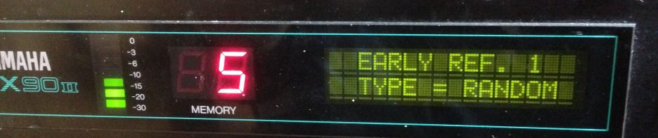
A colleague donated his old effects rack to the college. Mostly digital boxes that might now be considered “vintage”. Being a fan from way back, I was eager to fire up the Yamaha SPX90II. We observed that the display would flash briefly and the unit was non-functional. On inspection it was obvious that some of the electrolytics in the PSU had failed, or were approaching failure. Now you might think “Oh that’s easy, replace them all”. Actually we should replace them all, but the hope would be that nothing else in the circuit had failed and was stressing the capacitors.
DANGER! Multiple high voltages inside
Even if it looks like the regular failure mode of electrolytic capacitors (leaking with age), it is still wise to consult the service manual for clues about other things that might have caused the failure. However the PSU information in the service manual is poor (no levels) so I’ve posted a schematic I found for it. It’s a switching power supply, so even more care than usual needs to be taken than with linear supplies. The rule “touch nothing on the supply side of the transformer” applies here. Of note is C11 which is before the transformer (see schematic below). The original has an insulated top. Your replacement probably won’t! The voltage on it is 90 VAC at a fairly low current. If you’re lucky, that could be very painful. More likely you will be injured or killed. SO TOUCH NOTHING!!!! So it’s wise to put insulating tape on the replacement in case a future tech might touch it, or it ends up touching the casing while squashed into a rack.
Another assumption might be that all the brown goo is leakage from the capacitors. It’s not! It’s glue used to stabilise the components. A good idea to extend their life, given that they’re vibrating. I haven’t figured out what to replace it with. In the pictures below you can see some good examples of failed capacitors versus perfectly fine capacitors with glue on them. One had obviously burst, while others had to be removed from the board before it could be seen that they were about to burst. So this is really why it’s wise to replace them all in a PSU. They’re cheap, the unit is open and you cannot be certain with a 30 year old unit that all the electrolytic are fine- especially in a PSU where they are working hard!
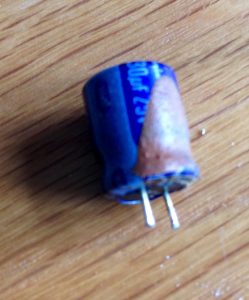
This capacitor is OK, the brown stuff is just aged glue.
This capacitor looked OK at first, the dents were only visible after it was removed.

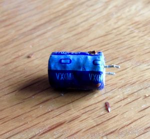
Definitely failed!

Notice the bulging. Leaked dielectric was observed under it after it was removed. Notice the insulated top. 90VAC on this if it is metal- so BE CAREFUL!
Having said that, I didn’t change any capacitors on the main or AD board as Yamaha calls it. They looked fine, the unit tested OK once the PSU was repaired, and life’s too short to waste on the mythical advantages of “capacitor upgrades”!
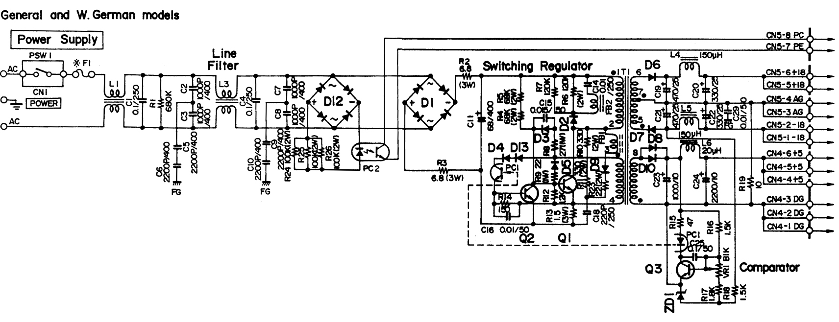
PSU schematic
You can download the service manual here. The electrolytic capacitors in the PSU are:
C11 = 68uF 400WV (this means peak operating voltage)
C19, 21 = 470uF 25V
C22, 20 = 330uF 25V
C23 = 1000uF 10v
C24 = 2200uF 10V
It’s the service manual for the SPX90 mark 1. The two units are identical apart from extended memory for the delays in the mark 2. Apparently a mark1 can be upgraded to mark 2 be replacing the EPROM IC151. I’ve never seen this done.
This unit passed all of the tests, except for the panel buttons which seem to double trigger occasionally. I’m hoping with use this will resolve itself. Removing the front panel is quite awkward. The output level switch needed a quick spray and exercise with Servisol to clean out dirt. It’s not a sealed unit so this was easy to do, should be good for another 10 years or so.
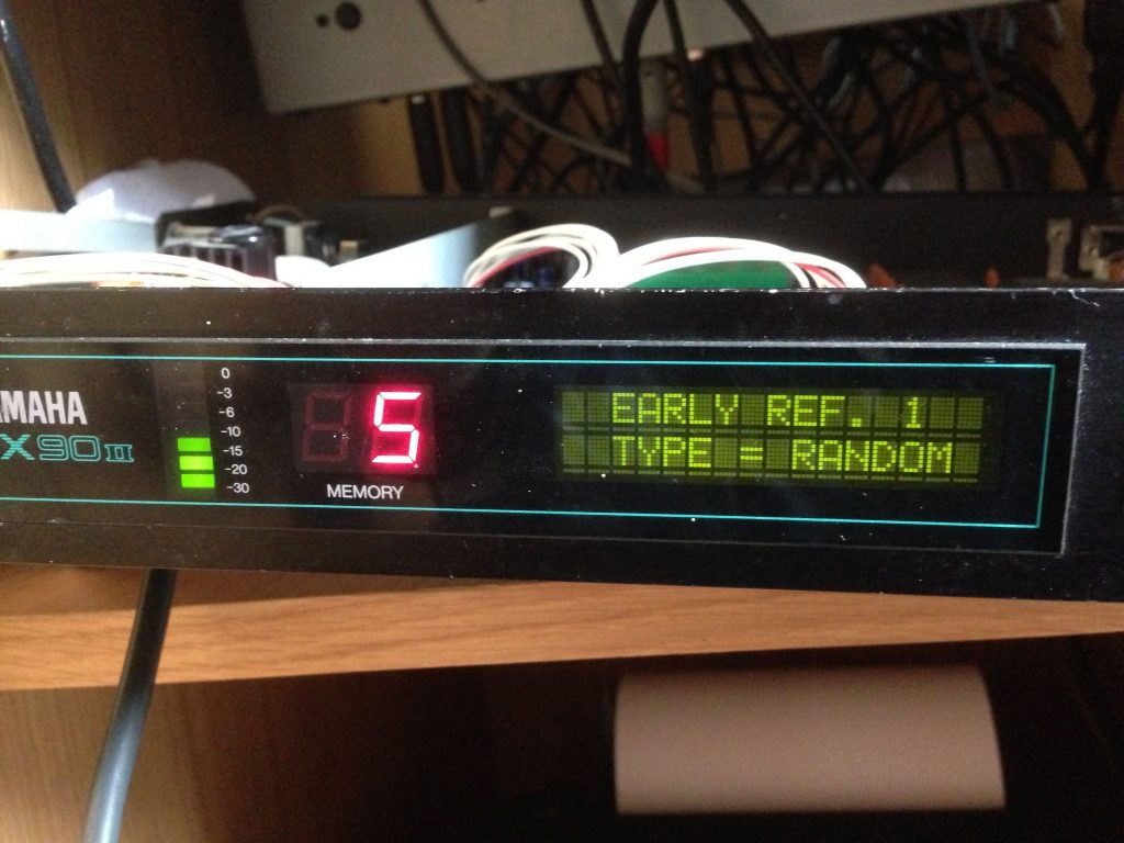
It lives! YAY!! The joys of the Random Early Reflections algorithm 🙂
Finally, thanks to the good folks on this Gearslutz thread, my source for a lot of the information above.
You sir, have used the specs for the German model…
Not sure what you’re getting at here, you didn’t finish the statement?
My schematic shows different a different value for C11 than what you have here. On mine there’s a General/West German models section and a Japanese, Canadian & U.S. models section. On the Japanese, Canadian & U.S. models section of the schematic C11=150uF/200WV The rest are the same as what you have listed here. I have five U.S. units in my possession and in all of them C11 is 150uF/200WV.
Great write up!!
I went to order caps at Dig-iKey- They ask for the “ESR” rating?
Suggestions?
Thank you!!
Low ESR and, for longer life, a higher voltage rating than the old one.
Hey Tomas,
Can the transformer be wired to 240v or 120v or 100v?
It’s an SMPSU- check the input voltage specs.
Anyone have a list of all axial diode values or NTE equivalents for the US version?
You can find it in the service manual link below. On page 18 are the codes for each regional variant.
https://www.synthxl.com/wp-content/uploads/2018/03/Yamaha-SPX-90-Service-Manual.pdf
Thank you so much. I was hoping someone had posted all NTE equivalents by now?
I’m at the point where I have high DC voltage going into the X-former but none coming out. Trans does have resistance and is def not open.
I have the same C11 value as you, would you be willing to give me a list of all capacitor replacements, or a list of capacitor replacements for the power supply section. I can pay for it.Thank you.
Hi bob. I’ve listed the values I used in the main blog post, for EU model. Check the service manual for the regional variations if any.
Ok thank you for your reply, my model is exactly european VA81410.